 English
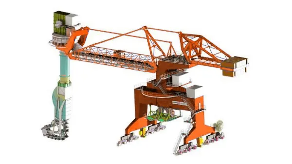
Just let we know what you want, and we will get in touch with you as soon as possible!

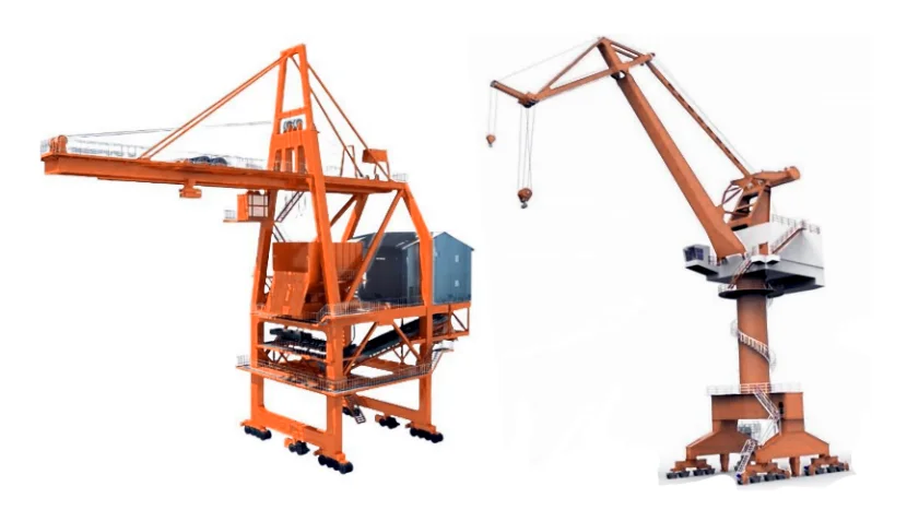
Screw Ship Unloader Parts List – Explained from Practical Site Experience
After working with screw ship unloaders on coal, grain, and lime terminals, one thing becomes very clear: the reliability of a screw ship unloader depends far more on its parts design and detailing than on its nameplate capacity. On paper, many systems look similar. On site, the differences show up in wear rate, downtime, dust leakage, and how easy the machine is to operate and maintain.

Below is a practical, experience-based breakdown of the main parts of a screw ship unloader, written from the point of view of how these machines actually behave in daily port operation.
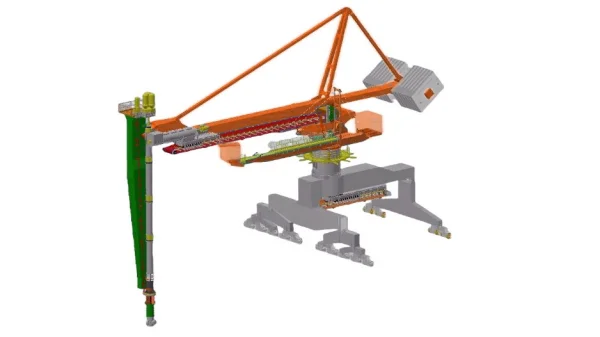
1. Intake Screw (Vertical or Inclined Screw)
The intake screw is the heart of the unloader and the first component that meets the material inside the ship’s hold.
In real operation, this screw does most of the hard work:
- Penetrating compacted coal or grain
- Handling uneven material levels
- Withstanding impact from tramp material
From experience, wear protection matters more than screw diameter alone. For coal and abrasive materials, hardfaced flights or Hardox-lined edges can double service life. For grain or cement, smoother flight surfaces help maintain steady flow and reduce power spikes.
Common issues on site:
- Flight edge wear leading to reduced capacity
- Bending due to improper positioning or ship movement
2. Horizontal Transfer Screw
Once material is lifted from the hold, it is transferred by a horizontal screw to the discharge point.
This section often looks "safe" on drawings but is actually where many blockages occur—especially with wet coal or fine cement. A slightly larger pitch, good liner selection, and proper speed control make a noticeable difference in daily operation.
Operators often prefer:
- Replaceable liners inside the trough
- Access covers for quick inspection and cleaning
3. Screw Trough and Housing
The screw housing is what makes the screw unloader a truly enclosed and dust-controlled system.
In practice:
- Poor flange sealing = dust leakage
- Thin housings = deformation over time
Well-designed housings use:
- Thick plate construction
- Bolted, gasketed inspection covers
- Internal wear liners for abrasive cargoes
This is especially critical for quicklime and cement, where dust escape is not acceptable.
4. Drive System (Motors, Gearboxes, Couplings)
The drive system is where operating cost and reliability meet.
Most medium-capacity screw unloaders use:
- Electric motors (200–500 kW range for ~1,000 t/h)
- Heavy-duty gearboxes with high service factors
From maintenance experience, the most important points are:
- Proper torque limitation to avoid screw damage
- Easy gearbox access for oil checks and replacement
Flexible couplings help absorb shock loads when material flow is uneven.

5. Telescopic or Articulated Boom Structure
The boom assembly allows the screw to reach different parts of the ship’s hold.
In real port conditions, this structure must handle:
- Constant repositioning
- Wind loads
- Vibration from continuous screw rotation
Reliable systems use:
- Box-type welded booms
- Slewing bearings with proven sealing
- Hydraulic or electric telescoping mechanisms
Poor boom stiffness often shows up as vibration at high throughput.
6. Slewing and Luffing Mechanisms
Slewing and luffing allow the unloader to cover the full hold area without moving the ship too often.
From operator feedback:
- Smooth, slow-speed control is more important than fast movement
- Position accuracy reduces idle time
These systems typically include:
- Slewing bearings
- Gear drives or hydraulic motors
- Limit switches and safety interlocks
7. Discharge Chute or Conveyor Interface
The discharge section connects the screw unloader to downstream conveyors or hoppers.
In practice, this area must:
- Absorb continuous material flow
- Stay sealed under negative pressure (dust control)
Wear liners and flexible connections are strongly recommended, especially when connecting to belt conveyors or mobile hoppers.
8. Dust Collection and Sealing System
Although often listed as “auxiliary,” dust control components are essential parts of a screw ship unloader.
These include:
- Sealed covers and skirts
- Dust extraction hoods
- Connection points for bag filters or central dust systems
For lime, cement, and grain, this system determines whether the unloader can actually operate in modern ports.
9. Hydraulic System (If Applicable)
Some screw unloaders use hydraulics for:
- Boom luffing
- Telescoping
- Positioning adjustments
Key practical considerations:
- Hose routing to avoid mechanical damage
- Easy access to cylinders for seal replacement
- Hydraulic failures are often small but cause long downtime if access is poor.

10. Control System and Instrumentation
The control system ties everything together.
From real-world operation, the most useful features are:
- Variable speed control for screws
- Load monitoring to prevent overload
- Simple, operator-friendly HMI screens
Overly complex automation can actually slow down fault diagnosis on site.
A screw ship unloader is not just a "screw in a boom." It is a system where every part—from the flight edge to the gearbox seal—affects uptime, dust control, and operating cost.
From practical experience:
- Invest more in wear protection and sealing
- Design for easy access and maintenance
- Match screw design to the actual material, not just nameplate density
When these details are done right, a screw ship unloader becomes one of the cleanest and most reliable bulk unloading solutions available for coal, grain, cement, and lime ports.
- How to Choose the Right Ship Unloader for Coal, Grain, and Cement Ports
- Screw Ship Unloader for Dust-Free Bulk Handling
- Screw Ship Unloader vs. Grab Ship Unloader: A Comparison
- Large-capacity Coal Ship Unloader
- Continuous Ship Unloader for Bulk Materials Handling
- Mechanical Ship Unloader For Bulk Material Unloading

Table of Contents
Leading Mobile Bulk Material Handling Equipment Manufacturer in China. A high-tech enterprise specializing in R&D and manufacturing of stacker conveyors, ship loaders, and bucket wheel reclaimers. We provide comprehensive mobile solutions, including mobile hopper feeders, truck unloaders (surface feeders), and transfer conveyors, alongside high-performance mobile crushing and screening plants for global bulk material processing.
How to Contact
- WhatsApp: +8617821512097
- E-mail: [email protected]
-
 Add: China