 English
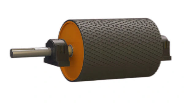
Just let we know what you want, and we will get in touch with you as soon as possible!
Belt Conveyor Pulley Shell: Complete Design & Fabrication Guide
Here's a focused, engineer-ready reference for the pulley shell (drum): design purpose, sizing rules, materials, fabrication, lagging options, inspection, balancing and drawing/QA notes. Use this as a checklist for engineering, procurement and workshop handover.

1) Function & quick overview
The pulley shell (or drum) is the cylindrical outer part of the pulley that contacts the belt (or the lagging). It:
- Transmits traction from shaft to belt (drive pulley) or redirects belt (bend/tail/snub).
- Supports lagging and takes radial belt loads.
- Transfers loads to end discs/hubs and hence to the shaft.
Core design goals: adequate stiffness (limit deformation), long fatigue life, good wear resistance, easy manufacture and serviceability.
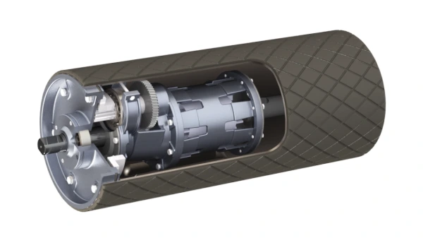
2) Typical geometry & components
- Outer diameter (D): specified by pulley type (common: 200–1800 mm).
- Shell thickness (t): plate rolled to make drum; determined by bending stiffness and local loads.
- Length (face width, B): typically equals belt width + tracking margin + lagging allowance.
- End discs: welded to shell; connect to hub.
- Hubs: welded or keyed to end discs to connect to shaft (shrink-fit or bolted).
- Inspection ports / grease holes: optional, for internal inspection/drainage.
- Drainage / vent holes: near ends to prevent water accumulation if used outdoors.
3) Material choices
- Common: ASTM A283, A36, St37 / Q235 / S235JR: low-medium carbon structural steel for shell.
- Higher grade: S355 / 16Mn for thicker shells or heavy-duty use.
- For corrosive environments: stainless steel (304/316) or carbon steel with protective coatings.
- Plate thickness depends on diameter and load: see next section.
4) Shell thickness sizing (practical rules & checks)
Exact design requires structural analysis; practical rules-of-thumb used in industry for preliminary sizing:
Rule-of-thumb ranges
- Small pulleys (D < 300 mm): t ≈ 4–8 mm.
- Medium (300 ≤ D ≤ 800 mm): t ≈ 6–12 mm.
- Large (D > 800 mm): t ≈ 10–20 mm or more.
Design checks
- Hoop / circumferential stress from welding and thermal effects: check by standard plate formulas.
- Local bending/wave between stiffeners: if long face widths, provide internal stiffeners or longitudinal ribs.
- Buckling: check shell plate for local buckling between stiffeners under compressive loads. Use classical shell buckling formulas or FEA for risky designs.
Stiffness requirement
Ensure radial deformation under full belt load won't exceed belt tracking/tensioning limits (typical maximum rim deflection often < 0.5–1.5 mm depending on belt system). Use beam-on-elastic-foundation or FEA for accurate deflection.
If you want, I can run a worked thickness calculation for your pulley if you give D, face width, belt load (radial) and material.

5) Welding & fabrication best practices
- Plate rolling & seam weld: roll shell plate with minimum number of longitudinal seams; full-penetration weld recommended.
- End disc weld: continuous circumferential fillet or full-penetration weld to end discs; ensure smooth transition for lagging.
- Preheat & interpass: use appropriate preheat for thicker plates or higher-carbon steels to avoid cracking.
- Dimensional control: maintain concentricity and straightness; use jigs/fixtures during welding.
- Stiffeners / ribs: add internal longitudinal ribs or annular stiffeners for long widths or high loads. Place ribs near bearing faces to support end loads.
- Drilling / holes: avoid excessive holes in shells that reduce stiffness; provide drain/inspection holes only where needed.
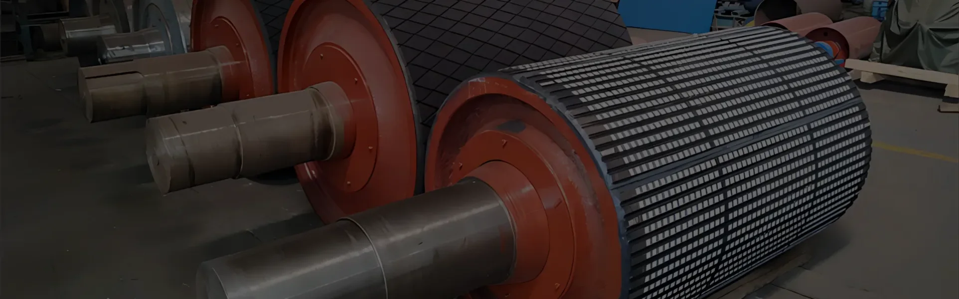
6) Lagging & shell surface options
Lagging improves traction, protects the shell and increases life. Options:
Rubber lagging (most common)
- Herringbone / chevron / diamond patterns for drainage and grip.
- Bonded (hot-vulcanized or cold-bonded) or mechanically clamped.
Ceramic tile lagging
- For very abrasive belts/materials; tiles embedded in rubber matrix.
Polyurethane
- Wear-resistant where rubber fails (oil/heat resistance).
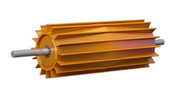
Bare steel shell
- Used with steel-to-steel contact or where lagging not required; requires corrosion protection and frequent inspection.
Design note: lagging thickness typically 6–12 mm; account for it in pulley diameter and balancing.
7) Corrosion protection & surface finish
- Paint (epoxy/alkyd) for general outdoor use after surface prep (blast to Sa 2.5).
- Galvanizing for long-term corrosion resistance; consider distortion from hot-dip galvanizing on tight tolerances.
- Nitriding / hard facing on contact areas where wear is extreme (less common for shell).
- Surface finish: smooth profile for easy lagging; radius transitions at end discs.
8) Mounting, alignment & balance
- Concentricity: shell concentric to hub/shaft within a small tolerance (typical runout < 0.5 mm TIR for large pulleys).
- Balance: static and dynamic balance after lagging fitted. Specify balance grade (G6.3/G16 depending rpm).
- Mounting holes: align hub and end disc holes for accurate shaft attachment; use dowels or precision reaming where required.
- Clearances: ensure sufficient clearance to idlers and structure when considering thermal growth and paint thickness.
9) Inspection & NDT
- Dimensional: concentricity, face width, shell thickness and weld quality.
- Visual weld inspection: fillet size, fusion, spatter, undercut.
- NDT: magnetic particle (MPI) or dye-penetrant on critical welds; ultrasonic on thick shells if required.
- Balance test: dynamic balancing at final assembly speed or at least at 75–100% operating rpm.
- Coating checks: adhesion, thickness.
10) Drawing notes & specification items to include
- Shell material spec and plate grade (e.g., S355JR).
- Shell outer diameter (nominal) and planned tolerance (e.g., +0 / -1 mm), and note lagging allowance.
- Shell plate thickness and tolerance (e.g., 10 ±0.5 mm).
- Weld types and weld sizes; post-weld heat treatment if required.
- Internal stiffener/ rib locations and dimensions.
- Drain/inspection hole locations and sizes.
- Surface finish before lagging (Ra spec).
- Painting/galvanizing spec and blast cleanliness.
- Balancing grade after assembly.
- NDT requirements and acceptance criteria.
- Weight (approx) and center of gravity location for lifting.
11) Common failures & how to prevent them
- Shell cracking at welds: use correct welding procedure, preheat, and post-weld treatment.
- Excessive deflection: increase thickness, add stiffeners, or reduce unsupported span.
- Corrosion under lagging: ensure proper drainage, use corrosion-resistant coatings, seal edges.
- Loose lagging: use correct bonding method (hot-vulcanize or mechanical) and ensure surface prep.
- Imbalance/vibration: balance after final assembly and lagging; control concentricity during fabrication.
12) QA checklist before release
- Material mill certificates available.
- Dimensional inspection: diameter, width, concentricity.
- Weld inspections (visual + MPI/DPI where required).
- Shell plate thickness and stiffener placement verified.
- Lagging prepared or specified (method, pattern, thickness).
- Balance test results documented.
- Surface protection applied per spec.
- Lifting & handling points marked.
If you want, I can:
run a shell thickness & stiffener calculation for a pulley (give me D, face width, radial belt load, material),
- produce a bolt-up drawing note set for procurement, or
- create a quick inspection checklist PDF you can download.
Tell me which and I'll do it right away.
- Belt Conveyor Pulley Shaft
- Belt Conveyor Pulley Part
- Belt Conveyor Pulley Lagging Procedure
- Belt Conveyor Pulley Lagging Materials
- Standard Belt Conveyor Pulley Types
- Heavy Duty Belt Conveyor Pulley Structure

Previous: Belt Conveyor Pulley Part
Table of Contents
Leading Mobile Bulk Material Handling Equipment Manufacturer in China. A high-tech enterprise specializing in R&D and manufacturing of stacker conveyors, ship loaders, and bucket wheel reclaimers. We provide comprehensive mobile solutions, including mobile hopper feeders, truck unloaders (surface feeders), and transfer conveyors, alongside high-performance mobile crushing and screening plants for global bulk material processing.
How to Contact
- WhatsApp: +8617821512097
- E-mail: [email protected]
-
 Add: China